-

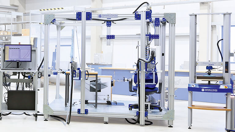
- Impact testing device for tests according to EN 61730-2
Device for shock tests
Device for impact tests according to EN 61730-2
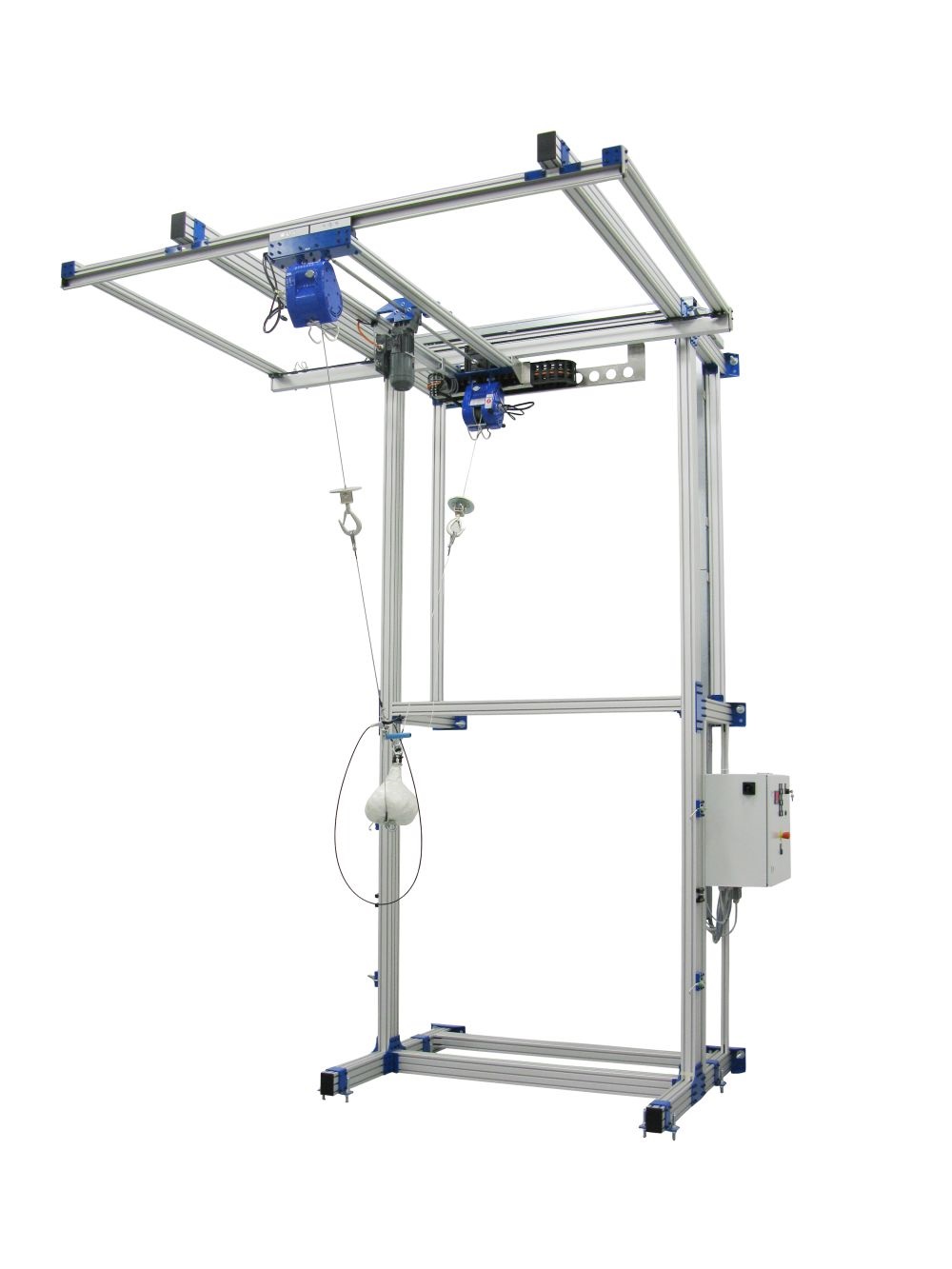
The test bench consists of the following components:
1.) Frame (standing firm on the ground and fixation of the upper bearers)
Main measurements are according to the standard DIN EN IEC 61730-2 (photovoltaic module safety qualification). The vertical supports (to which the modular tool holder is attached) are anchored in the floor. The upper supports which hold the carrier system (see 2.) are anchored in the wall. Shear connectors are used for fixation. The necessary installation kit comes with the scope of delivery. 4 quick releases are mounted to the frame, linking to the upper and lower horizontal section of the trolley. This arrangement requires for test pieces of little height the use of the same trolley. The transportation trolley has to be placed in front of the frame that the planned point of impact is located in its middle.
2.) Carrier system with leads and lifting equipment
To ensure that the transportation trolley with the test pieces can be brought into its test position easily, it is necessary to move the impact object with its components laterally out of the area in which the trolley has to be moved. The components are placed on two horizontal carriers, which are in about 4.1 m height. The first carrier holds the cable winch of the impact object. This allows the positioning of the impact object in a standardized distance to the test piece and the desired height. The second carrier has to be mounted with a distance of 2 m and carries the cable winch for the amplitude of the impact object. The carrier devices on both carriers are linked mechanically and proceed synchronically. The length of the carriers is according to the distance of the steel profiles of about 3 m.
3.) Impact object with release mechanism
The impact object is according to the image 4 of the above named test standard. For visual control of the impact height the center of gravity is marked. Other than displayed in the image, the suspension device has been equipped with an eyelet to avoid crashes of the impact object. The deflecting cable winch is connected with the help of an installation, which is operated by a Bowden cable over a handle. By simple pressing the impact object is released. Displays show the position of both cable winches and allow a correct set up of the deflection according to a table. We create the table when commissioning the machine and deliver it to the operator.
Notes:
- The installation requires a ceiling height of at least 4.5 m
- We will place the floor and wall holes for anchoring. Costs for the placement by the client or third parties are not included and will not be accepted
- Both cable winches are intended to be electro hoists. The operation of the electro drives, as well as the altimeter displays are centrally located at the wall
- The originally discussed set up (lifting of the impact object for changing of test piece) has been replaced by a lateral displacement next to the test piece in favor of security
- The impact energy at stage three of testing (deflection up to a horizontal distance of 1220mm) depends, according to our opinion, on the current length of the wires, since it depends on the drop height which is again influenced by the length of the wires